Flow Control Valve Circuit Diagram Flow Control Valve Diagra
Speed control circuits Flow priority regulator valves circuit valve control hydraulic power Flow control valve circuit diagram
Flow Control Valve (Meter-out) Circuit – ManufacturingET.org
Circuit meter flow control valve cylinder extension manufacturinget retraction pressure side Flow control hydraulic valves pressure compensated circuit symbology controls Asco redhat 2 wiring diagram
How flow control valves work
Flow control valve circuit diagramCheck valve symbol Principle engineeringlearnHydraulic flow control valves.
Flow control valve circuit diagramValves pneumatic Flow control valves hydraulic symbology 204, 55% offValve flow control.

Pressure-compensated valves
Solenoid wiring asco redhat circuits circuitdigest schematicsPressure compensated flow regulator valves • related fluid power Flow control valve hydraulic symbol valves system pressure compensated diagram parker wayWhat is a flow control valve and what are the functions of flow control.
Flow control valve circuit diagramFlow control valve: definition, types, components & working principle Circuits actingPressure compensated non valves flow control hydraulic schematic needle diagram troubleshooting.

Flow control valve
Pressure flow compensated regulator valves valve control circuit hydraulicPressure compensated schematic flow control hydraulic valves valve diagram orifice troubleshooting fig Flow control valve circuit diagramFlow control series valve.
Flow control valve (meter-out) circuit – manufacturinget.orgFlow control valve diagram Control flow diagramPriority flow regulator valves • related fluid power.

Control flow diagrams
Flow control diagramNon-pressure-compensated valves Control station and control valve in the process piping[diagram] powers 3 way valve diagram.
Schematic diagram of the flow control valveSchematic diagram of flow/pressure valve control: (a) meter-out flow Flow control valves diagram, types, working & usesFlow control valve.

Valve working principle globe plug labels basic
[diagram] 22re valve diagramFlow control valve circuit diagram Control valves flow hydraulic work animation valve diagram system mechanical wiringFlow control valves.
Flow control valve circuit diagramPiping station process Flow control valves.


Non-Pressure-Compensated Valves - Hydraulic Schematic Troubleshooting
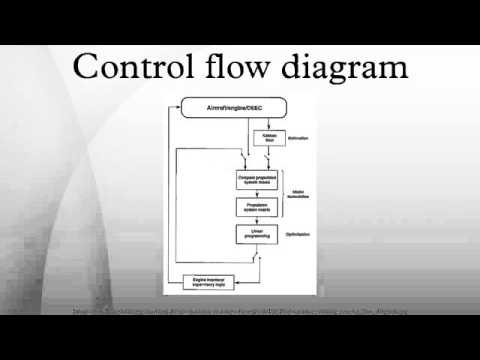
Control flow diagram - YouTube

Schematic diagram of flow/pressure valve control: (a) meter-out flow

Flow Control Valve Circuit Diagram

Flow Control Valve Diagram
![[DIAGRAM] Powers 3 Way Valve Diagram - MYDIAGRAM.ONLINE](https://i2.wp.com/assuredautomation.com/news-and-training/wp-content/uploads/2017/05/Pool-n-Spa-valves.jpg)
[DIAGRAM] Powers 3 Way Valve Diagram - MYDIAGRAM.ONLINE

Flow Control Valves Diagram, Types, Working & Uses - BERMAD